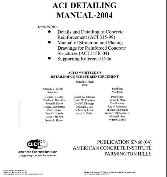
ACI Detailing Manual
Product Details
ACI Detailing Manual-2004 SP6604 (ACI-SP-66(04)) is a must-have resource and reference that provides answers to many drawing detailing questions asked by design engineers, architects, contractors, detailers, drafters, and engineering students. It is divided into three sections as follows:

"Details and Detailing of Concrete Reinforcement (ACI 315-99)”
"Manual of Engineering and Placing Drawings for Reinforced Concrete Structures (ACI 315R-04)”
Supporting References
ACI Detailing Manual-2004 establishes standards of practice for both structural and placing drawings and defines responsibilities for:
Architects
Engineers
Detailer / Drafter
ACI Detailing Manual-2004 also illustrates methods for presenting necessary design information through 50 oversized, fold-out drawings of highway and non-highway structures. Structural drawings conform to "Building Code Requirements for Structural Concrete (ACI 318-02/318R-02)” and all drawings were prepared with the assistance of the Federal Highway Administration, California Department of Transportation, and Concrete Reinforcing Steel Institute. ACI Detailing Manual-2004 SP6604 (ACI-SP-66(04)) has supporting reference data for reinforcing bars, wires, bar supports, spirals, mathematical formulas and tables, and common symbols and abbreviations.
The table of contents for ACI Detailing Manual-2004 SP6604 (ACI-SP-66(04)) is as follows:
DETAILS AND DETAILING OF CONCRETE REINFORCEMENT (315-99)
Part A—Responsibilities of the architect/engineer
Chapter 1—Structural drawings
1.1—General
1.2—Drawing standards
1.3—Structural drawings—Buildings and other structures
1.4—Structural drawings—Highway and transportation structures
Chapter 2—Standards of practice
2.1—General
2.2—Tolerances
2.3—Bar lengths
2.4—Hooks and bends
2.5—Beams and girders
2.6—Columns
2.7—Development and splices of reinforcing steel
2.8—Joint details
2.9—Reinforcing steel supports
2.10—Special details for seismic design of frames, joints, walls, diaphragms, and two-way slabs
2.11—Corrosion-resistant coatings for reinforcing steel
Part B—Responsibilities of the detailer
Chapter 3—Placing drawings
3.1—Definition
3.2—Scope
3.3—Procedure
3.4—Drawing standards
3.5—Building drawings
3.6—Highway drawings
3.7—Detailing to fabricating standards
Chapter 4—Fabricating practice standards
4.1—Fabrication
4.2—Extras
4.3—Tolerances
Chapter 5—Supports for reinforcing steel
5.1—General
5.2—Types of bar supports
5.3—Side form spacers and beam bolsters
5.4—Placing reinforcing steel supports
Chapter 6—Computer-assisted detailing
6.1—Use of computers in detailing
6.2—Placing drawings
6.3—Ordering procedures
Chapter 7—Recommended practices for location of bars designated only by size/spacing
Chapter 8—Glossary
Chapter 9—References,
9.1—Reference standards
9.2—Cited references
MANUAL OF STRUCTURAL AND PLACING DRAWINGS FOR REINFORCED CONCRETE STRUCTURES (ACI 315R-04)
S-1—Foundations (Structural Drawing)
P-1—Foundations (Placing Drawing)
P-1A—Foundations (Placing Drawing)
S-2—Columns (Structural Drawing)
P-2—Columns (Placing Drawing)
S-3—One-Way Concrete Joist Floor (Structural Drawing)
P-3—One-Way Concrete Joist Floor (Placing Drawing)
S-4—Flat Slab Floor (Structural Drawing)
P-4—Flat Slab Floor (Placing Drawing)
S-5—Flat Plate Slab Floor (Structural Drawing)
P-5—Flat Plate Slab Floor (Placing Drawing)
S-6—Beam and Girder Framing (Structural Drawing)
P-6—Beam and Girder Framing (Placing Drawing)
SP-7A—Slipform Concrete Walls (Combined Structural-Placing Drawing
SP-7B—Slipform Concrete Walls (Combined Structural-Placing Drawing
S-8—Turbine Pedestal (Structural Drawing)
P-8—Turbine Pedestal (Placing Drawing)
S-9—Foundations—CAD Generated (Structural Drawing)
P-9—Foundations—Cad Generated (Placing Drawing)
S-10—Seismic Frame Beams, Flat Plate Floor (Structural Drawing)
P-10—Seismic Frame Beams, Flat Plate Floor (Placing Drawing)
TYPICAL DRAWINGS FOR HIGHWAY STRUCTURES
H-1—Slab Bridge—General
H-1A—Slab Bridge Abutment Details
H-1B—Slab Bridge bent Details
H-1C—Slab Bridge Deck Slab and Parapet Details
H-2—Precast AASHTO I-Beam Sections—General
H-2A—Precast AASHTO I-Beam Sections— Reinforcing Steel
H-2B—Precast AASHTO I-Beam Sections—Pretensioned Strands (40 to 55 ft Spans)
H-2C—Precast AASHTO I-Beam Sections—Pretensioned Strands (60 to 80 ft Spans)
H-2D—Precast AASHTO I-Beam Sections—Pretensioned Strands (90 to 120 ft Spans)
H-2E—Precast AASHTO I-Beam Sections—Post-Tensioned Strands (60 to 90 ft Spans)
H-2F—Precast AASHTO I-Beam Sections—Post-Tensioned Strands (90 to 120 ft Spans)
H-3—Precast/Prestressed Concrete I-Beam Bridge—General
H-3A—Precast/Prestressed Concrete I-Beam Bridge—Abutment Details
H-3B—Precast/Prestressed Concrete I-Beam Bridge—Bent Details
H-3C—Precast/Prestressed Concrete I-Beam Bridge—Framing Plan and Deck Slab Details
H-3D—Precast/Prestressed Concrete I-Beam Bridge—Beam Details
H-3E—Precast/Prestressed Concrete I-Beam Bridge—Approach Slab and Reinforcing Steel Schedule
H-4—Rolled Beam Bridge—General
H-4A—Rolled Beam Bridge—Abutment Details.
H-4B—Rolled Beam Bridge—Bent Details
H-4C—Rolled Beam Bridge Deck—Slab Details
H-5—Precast Pretensioned Box Sections—General.
H-5A—Precast Pretensioned Box Sections—Details
H-6—Post-Tensioned Concrete Box Girder Bridge—General
H-6A—Post-Tensioned Concrete Box Girder Bridge—Abutment Details
H-6B—Post-Tensioned Concrete Box Girder—Bridgebent Details
H-6C—Post-Tensioned Concrete Box Girder Bridge—Girder Details
H-6D—Post-Tensioned Concrete Box Girder—Slab and Girder Reinforcement
H-6E—Post-Tensioned Concrete Box Girder Bridge—Miscellaneous Details
H-6F—Post-Tensioned Concrete Box Girder Bridge—Approach Slab
HE-7—Box Culvert (Structural Drawing)
HP-7—Culvert (Placing Drawing)
H-8—Cantilevered Retaining Wall—Type 1 (1200 to 9100 mm Heights)
H-8A—Cantilevered Retaining Wall—Type 1 (9700 to 10,900 mm Heights)
H-8B—Cantilevered Retaining Wall—Type 1A (1200 to 3600 mm Heights).
H-8C—Cantilevered Retaining Wall—Type 2 (1800 to 6700 mm Heights)
H-8D—Cantilevered Retaining Wall—Details
SUPPORTING REFERENCE DATA
Chapter 1—Reinforcing bars
1.1—Bar specifications
1.2—Welding of bars
1.3—Overall bar diameter
1.4—ACI standard fabricating tolerances for nominally square saw-cut bar ends
1.5—Coated reinforcing bars
1.6—ASTM specifications for coated bars
1.7—Design data for reinforcing bars
1.8—Detailing data for reinforcing bars
Chapter 2—Wires and welded wire fabric
2.1—Introduction
2.2—Designation of wire size
2.3—Styles of welded wire fabric
2.4—Epoxy-coated wires and welded wire fabric
2.5—Dimensions of welded wire fabric
2.6—Design data for welded wire fabric
Chapter 3—Bar supports
3.1—General
3.2—Side-form-spacers
3.3—Nonstandard bar supports
3.4—CRSI bar-support recommendations
Chapter 4—Spirals
4.1—Purpose
4.2—Definitions
4.3—Reinforcement recommendations
4.4—Size and pitch recommendations
4.5—Spacer recommendations
4.6—Weight (mass) of spirals
Chapter 5—Mathematical tables and formulas
5.1—Properties of the circle
5.2—Trigonometric formulas
Chapter 6 — Common symbols and abbreviations
6.1—Organizations
6.2—Stress and force designations
6.3—Structural steel designations
6.4—Bar supports
6.5—Parts of a structure (used in marks for structural members)
6.6—Common abbreviations
Chapter 7—References, p. 207
7.1—Referenced standards and reports
Download
http://s18.alxa.net/s18/srvs2/01/ACI...ing.Manual.rar