Structural Modelling Using SAP2000
The SAP2000 modeling comprises the following steps:
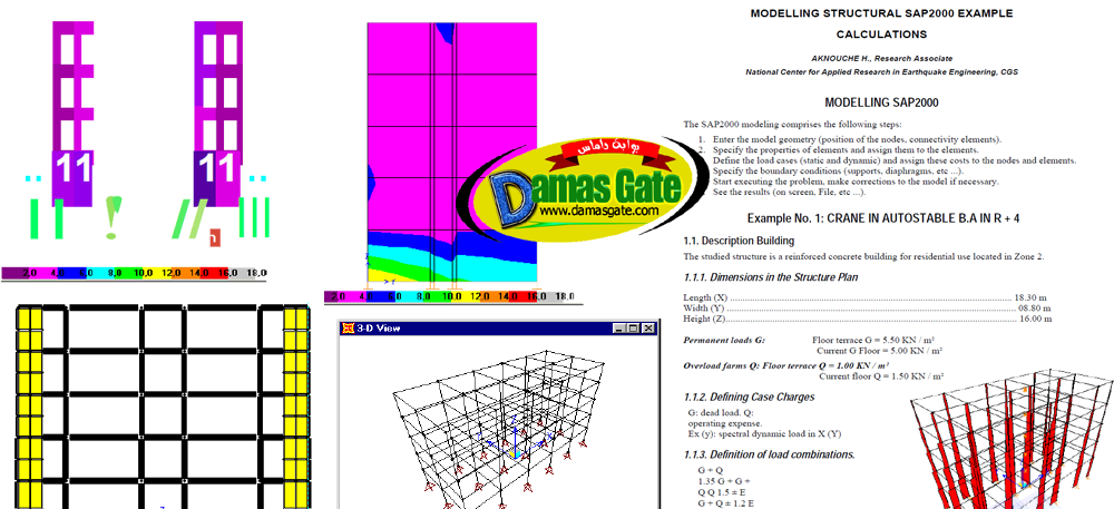
1. Enter the model geometry (position of the nodes, connectivity elements).
2. Specify the properties of elements and assign them to the elements.
3. Define the load cases (static and dynamic) and assign these costs to the nodes and elements.
4. Specify the boundary conditions (supports, diaphragms, etc …).
5. Start executing the problem, make corrections to the model if necessary.
6. See the results (on screen, File, etc …).The studied structure is a reinforced concrete building for residential use located in Zone 2.Description Building
Dimensions in the Structure Plan
Defining Case Charges
Calculation of Masses for Modal Analysis
Define the Geometry Model
Choice of Units
Choice of Units
Changing the geometry Base
Specifying Properties of the Elements
Definition of Material
Selection of Sections
Defining Sections
Assigning the Elements Structures
Viewing Information Model
Setting Case Charges
Case of Static Loads (Permanent and Exploitation)
Case of Seismic Loads
Static Equivalent Method
Method Modal Spectral Analysis (Response Spectrum)
Assigning Static Loads
Allocation charges Seismic
Combinations of Shares
Boundary Condition
Creating the Master Node
Constraints
Starting the Run
Display and Operating Results
Results Files
Viewing Results on Screen
Starting a Other Analysis