السلام عليكم
Engineering Spreadsheet, Software
Member Design – Reinforced Concrete Beam BS8110


Download
http://s18.alxa.net/s18/srvs2/02/003...eam.BS8110.rar
Engineering Spreadsheet, Software
Member Design – Reinforced Concrete Beam BS8110


BS 8110 is a British Standard for the design and construction of reinforced and prestressed concrete structures. It is based on limit state design principles. Although used for most civil engineering and building structures, bridges and water-retaining structures are covered by separate standards (BS 5400 and BS 8007.Prestressed concrete is a method for overcoming concrete’s natural weakness in tension. It can be used to produce beams, floors or bridges with a longer span than is practical with ordinary reinforced concrete. Prestressing tendons (generally of high tensile steel cable or rods are used to provide a clamping load which produces a compressive stress that balances the tensile stress that the concrete compression member would otherwise experience due to a bending load. Traditional reinforced concrete is based on the use of steel reinforcement bars, rebars, inside poured concrete.
Limit state design requires the structure to satisfy two principal criteria: the ultimate limit state (ULS and the serviceability limit state (SLS. A limit state is a set of performance criteria (e.g. vibration levels, deflection, strength, stability, buckling, twisting, collapse that must be met when the structure is subject to loads.
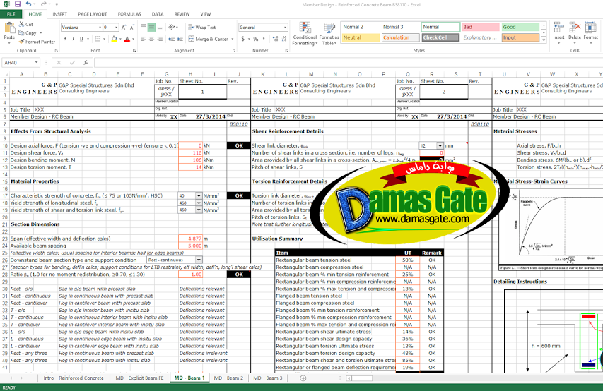
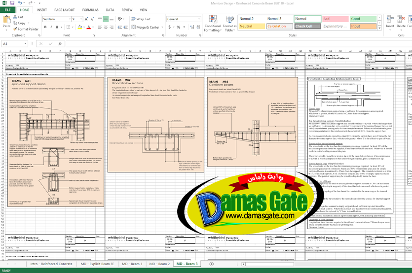
The following checks are performed by this Workbook:
Member Design – Beam
1 Rectangular Beam Singly Reinforced Bending Design
2 Rectangular Beam Singly Reinforced Neutral Axis Back-Analysis
3 Rectangular Beam Doubly Reinforced Bending Design
4 Rectangular Beam Doubly Reinforced Neutral Axis Back-Analysis
5 Flanged Beam Singly Reinforced Bending Design, Flange Neutral Axis
6 Flanged Beam Singly Reinforced Neutral Axis Back-Analysis, Flange Neutral Axis
7 Flanged Beam Doubly Reinforced Bending Design, Flange Neutral Axis
8 Flanged Beam Doubly Reinforced Neutral Axis Back-Analysis, Flange Neutral Axis
9 Flanged Beam Singly Reinforced Bending Design, Web Neutral Axis
10 Flanged Beam Singly Reinforced Neutral Axis Back-Analysis, Web Neutral Axis
11 Flanged Beam Doubly Reinforced Bending Design, Web Neutral Axis
12 Flanged Beam Doubly Reinforced Neutral Axis Back-Analysis, Web Neutral Axis
13 Rectangular or Flanged Beam Shear Design
14 Rectangular Beam Torsion Design
15 Rectangular Beam Combined Shear and Torsion Design
16 Rectangular and Flanged Beam Deflection Design
17 Rectangular or Flanged Beam Crack Width Estimation
Download
http://s18.alxa.net/s18/srvs2/02/003...eam.BS8110.rar